How can manufacturers of steel structure components that can be customized for various sets of equipment optimize the structural design of steel structure components to improve load-bearing capacity and lightweight?
In the customization and manufacturing of steel structure components for complete sets of equipment, optimizing the structural design to simultaneously improve load-bearing capacity and achieve lightweight is the core issue of balancing performance, cost and efficiency. This process requires combining material properties, mechanical principles, manufacturing processes and actual working conditions to achieve the goal through a systematic design strategy. The following detailed description of the specific methods from multiple dimensions:
1. Optimization based on material properties: Choose the right "foundation" to get twice the result with half the effort
The selection and reasonable application of materials are the prerequisites for structural optimization. The strength, toughness, density and other parameters of different steels vary significantly, and they need to be accurately matched according to the load-bearing requirements of the components, working environment and other factors.
Application of high-strength steel: Using low-alloy high-strength steel with higher yield strength (such as Q355, Q460, etc.) can reduce the material thickness under the same load-bearing conditions and directly reduce the deadweight of the structure. For example, a load-bearing beam was originally designed to use Q235 steel with a thickness of 20mm. After using Q355 steel, the thickness can be reduced to 16mm, the weight is reduced by 20%, and the bearing capacity is not affected.
Differentiated distribution of materials: According to the stress characteristics of each part of the structure, high-strength materials are used in high-stress areas and ordinary materials are used in low-stress areas to achieve "good steel is used on the blade". For example, high-strength steel is used in the stress-concentrated parts of the equipment base, while ordinary carbon steel is used in the auxiliary support part, which can not only ensure the overall strength but also control the cost and weight.
Exploration of new materials: In scenarios with extremely high lightweight requirements (such as mobile equipment steel structures), aluminum alloys or composite materials (such as carbon fiber reinforced resin-based composite materials) can be used in non-load-bearing parts to form a hybrid structure with steel. However, attention should be paid to the connection methods and compatibility of different materials to avoid structural failure due to electrochemical corrosion or mismatch of mechanical properties.
2. Topological optimization of structural form: making force transmission more "efficient"
Topological optimization is to find the optimal distribution form of materials according to loads and constraints in a given design space through mathematical algorithms, so as to achieve "removing the dross and retaining the essence", and ensure the load-bearing capacity while reducing weight.
Remove redundant materials: Use finite element analysis (FEA) software to simulate the stress state of the structure, identify the "redundant areas" with lower stress and cut them. For example, the traditional design of equipment columns is mostly solid structure. After topological optimization, it can be designed as a hollow lattice or thin-walled structure with reinforcement ribs, retaining enough material at the stress concentration point, reducing the material in the non-stress area, reducing the weight by more than 30%, and improving the stiffness.
Reference to bionic structure: Biological structures in nature (such as honeycombs and bird bones) have the characteristics of "lightweight and high strength", and their principles can be applied to steel structure design. For example, the panel of the equipment platform is designed as a honeycomb sandwich structure, and the core layer uses thin-walled steel, which not only reduces the weight, but also improves the overall load-bearing capacity through the dispersed load effect of the honeycomb structure.
Optimization of cross-sectional shape: The geometric shape of the component cross-section has a significant impact on the bearing capacity. Under the same cross-sectional area, the moments of inertia and section modulus of I-shaped, box-shaped, and circular sections are larger, and the bending and torsion resistance is better. For example, the drive shaft uses a hollow circular tube section instead of a solid round steel, and the torsion resistance is basically the same when the weight is reduced by 50%; the crossbeam uses an I-shaped section instead of a rectangular section, and the bending bearing capacity can be increased by 40% under the same dead weight.
3. Optimization of connection methods: Reduce "extra burden" and improve overall stiffness
The connection node is the weak link of the steel structure. An unreasonable connection method will increase the weight, reduce the overall stiffness, and even cause stress concentration. The optimization of the connection design needs to take into account strength, lightweight and construction feasibility.
Optimization of welded connections: Use continuous welds instead of intermittent welds to reduce the total length of the weld while ensuring the connection strength; for thick plate connections, use groove welds instead of fillet welds to reduce the weld volume and heat-affected zone, and reduce the additional stress caused by welding deformation. In addition, the position of welds is optimized through finite element analysis to avoid setting welds at stress concentration points and improve node reliability.
Refined design of bolt connections: The bolt specifications and quantity are accurately calculated according to the force size to avoid blindly using large specifications or too many bolts. For example, the flange connection of a certain equipment was originally designed to use 12 M20 bolts. After force analysis, it was adjusted to 8 M18 bolts, which not only met the strength requirements but also reduced the material consumption of bolts and flanges.
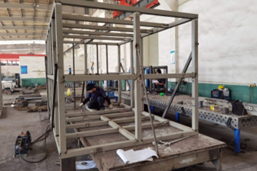
Integrated molding process: For complex components, overall bending, laser cutting and blanking processes are used to reduce the number of splicing. For example, if the frame structure of the equipment is spliced by multiple steel plates, the weight of welds and connectors will increase. However, by bending the entire steel plate into the frame body through a large bending machine, 70% of the splicing points can be reduced, the weight can be reduced by 15%, and the overall stiffness can be significantly improved.
4. Strengthening stiffness and stability: Avoid "instability due to lightness"
Lightweight design must be based on ensuring structural stiffness and stability, otherwise the bearing capacity may fail due to excessive deformation or instability.
Reasonable arrangement of reinforcing ribs: Reinforcing ribs (such as U-shaped and L-shaped ribs) are set on the surface of thin-walled components to improve local stiffness by changing the moment of inertia of the section. For example, the thin plate shell of the equipment is easy to deform when subjected to uniform load. After adding longitudinal and transverse reinforcing ribs along the force direction, the stiffness can be increased by more than 50% when the material consumption increases by 5%.
Verification and adjustment of stability: For slender rods, thin-walled components and other components that are prone to instability, their stability needs to be verified by Euler's formula. If necessary, lateral support is added or the cross-sectional shape is adjusted (such as changing the rectangular section to an I-shaped section) to increase the critical instability load without adding too much weight.
Reasonable application of preload: For bolt-connected load-bearing components, appropriate preload is applied to make the connector fit tightly, reduce relative deformation during work, and improve overall stiffness. For example, the connection bolts between the bearing seat and the base of the equipment can increase the stiffness of the joint surface by 20%~30% after applying preload.
5. Combination of simulation and experiment: Use data to "escort" the optimization effect
Structural optimization cannot rely solely on experience, but needs to be verified through simulation analysis and physical tests to ensure the reliability of the design scheme.
Finite element simulation analysis: In the design stage, ANSYS, ABAQUS and other software are used to establish a three-dimensional model to simulate the stress distribution, deformation and fatigue life under different loads and working conditions. The structural parameters (such as wall thickness, rib plate position, and cross-sectional size) are adjusted through multiple iterations until the balance point between "lightweight" and "high strength" is found. For example, the rotating arm of a welding robot has reduced its weight by 25% and its maximum stress by 10% after 5 rounds of simulation optimization, which fully meets the use requirements.
Physical test verification: Static load test, dynamic load test and fatigue test are carried out on the optimized prototype to verify its actual load-bearing capacity and durability. For example, the optimized load-bearing beam is loaded and tested by a hydraulic testing machine, and its yield load and limit load are recorded to ensure that it is not lower than the design standard; the dynamic load during the operation of the equipment is simulated by the vibration table test to check whether the structure resonates or deforms excessively.
Iterative improvement mechanism: Feedback test data to the simulation model, modify parameters (such as material properties, boundary conditions), and further optimize the design. For example, if the actual deformation of a component is found to be greater than the simulation result during the test, it is necessary to recheck whether the constraints of the model are consistent with the actual situation and adjust the structural design.
6. Collaboration between process and design: Make the design "landing" more efficient
Structural optimization needs to consider the feasibility of the manufacturing process, otherwise even the best design will be difficult to achieve. Manufacturers need to combine their own equipment capabilities and process characteristics to incorporate process requirements in the design stage.
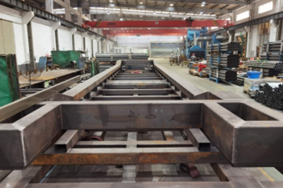
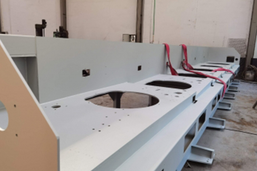
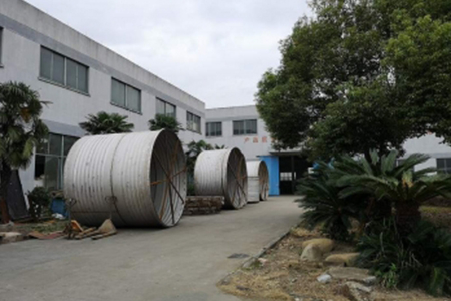
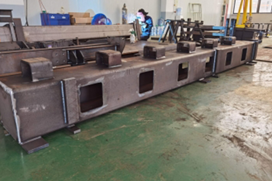
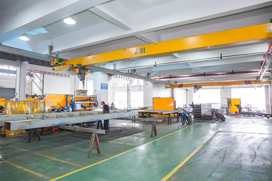
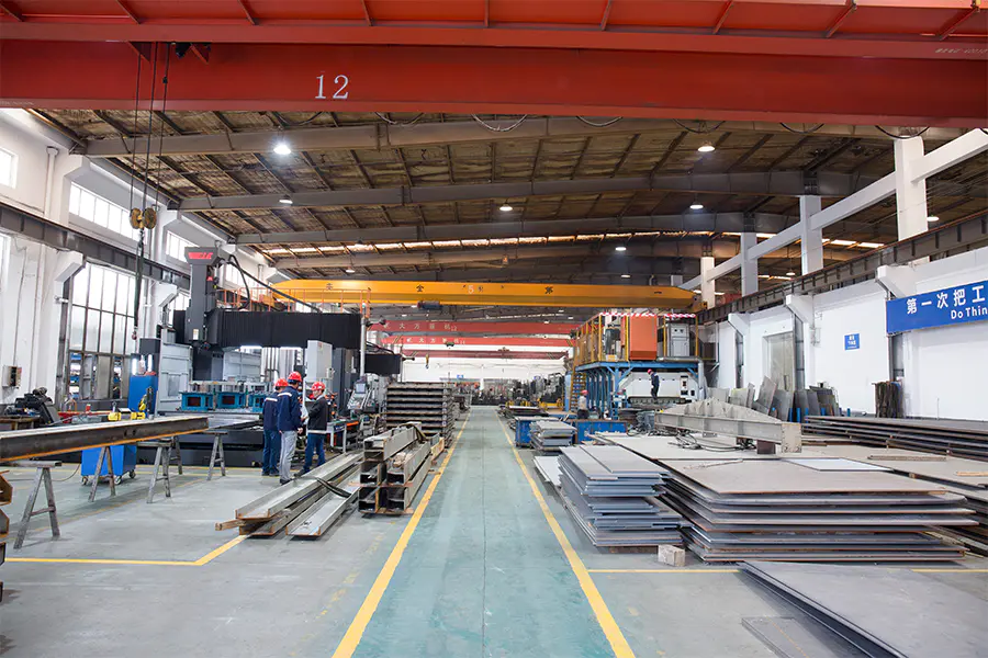
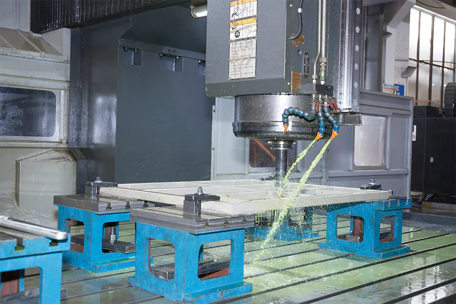
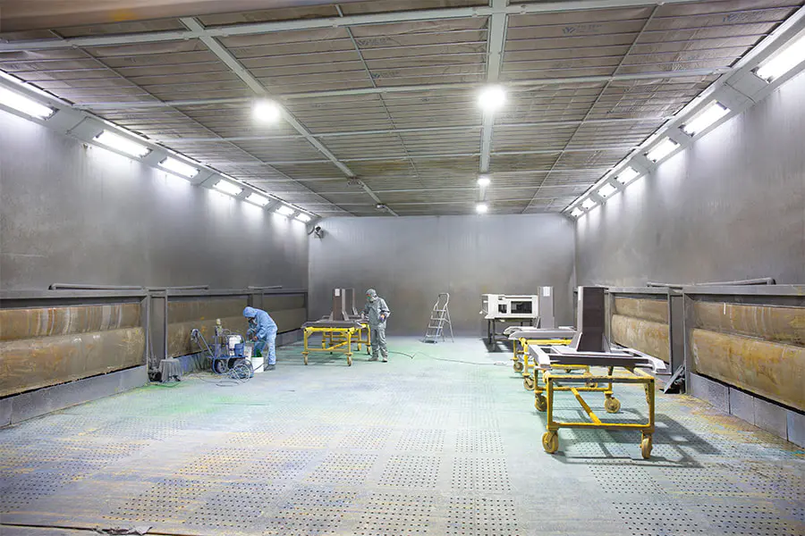
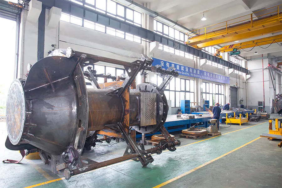
For example, Jiaxing Dingshi Machinery Manufacturing Co., Ltd can support the processing and manufacturing of complex structures with advanced equipment such as 15,000 square meters of indoor production space, 6 meters × 3.5 meters large gantry processing center, and 30 kW laser sheet cutting machine. Its 20 professional technical designers have strong drawing design conversion capabilities, and can accurately convert the optimized structural design into producible process drawings, ensuring that topology optimization, material selection and other solutions are implemented in actual production - such as using a 600-ton bending machine to achieve integrated molding of large thin-walled components and reduce splicing; through 50 welding equipment of various types and the superb skills of 60 certified welders, the strength and precision of complex welds are guaranteed, providing reliable process support for structural optimization.

