No.158, Baoqun Road, Yaozhuang Town, Jiashan County, Jiaxing City, Zhejiang Province , China
Content
TIG, MIG, and Stick welding impose fundamentally different requirements on the design, fabrication, and finishing of welding parts. The choice of welding process directly influences the part's geometry, surface quality, material thickness, joint configuration, and tolerance specifications. For professional welding parts customization, understanding these distinctions is not optional—it is the foundation of producing sound, cost-effective, and reliable welded structures. TIG welding demands the highest precision and cleanliness, MIG offers a balanced combination of speed and quality, while Stick welding tolerates the greatest variability but requires thicker sections and more robust joint designs. Each process excels in different applications, and the optimal part design varies significantly across them.
At the heart of the difference lies the heat source, shielding mechanism, and filler metal delivery. TIG (Gas Tungsten Arc Welding) uses a non-consumable tungsten electrode with separate filler rod, enabling precise control over heat input and weld pool. MIG (Gas Metal Arc Welding) employs a continuously fed consumable wire electrode combined with external shielding gas. Stick (Shielded Metal Arc Welding) uses a flux-coated consumable electrode that generates its own shielding gas and slag.
These fundamental differences cascade into every aspect of welding parts. For example, TIG-welded parts typically require edge preparation accuracy within ±0.5 mm and surface roughness below 1.6 μm Ra. MIG parts accept tolerances around ±1.0 mm, while Stick parts can function with ±2.0 mm or greater. The part thickness range also diverges: TIG excels on 0.5–6 mm sections, MIG handles 1–25 mm, and Stick reliably welds 3 mm to over 50 mm in a single pass.
The electrode type dictates the filler material format, which in turn affects part design. In TIG welding, the filler rod is manually fed into the weld pool, requiring accessibility and clearance for the welder's hand—this means parts must be designed with adequate open space around joints. The filler rod diameter typically ranges from 0.8 mm to 3.2 mm, matching the base material thickness.
MIG welding uses a spool-fed solid or cored wire with diameters from 0.6 mm to 1.6 mm. The continuous feed allows for higher deposition rates but requires a smooth, unobstructed wire path—parts with tight corners or deep grooves may impede the gun nozzle. Stick welding electrodes come in diameters from 1.6 mm to 6.4 mm, and the flux coating composition must match the base metal type. Stick electrodes are less sensitive to part geometry, as the welder can manipulate the rod angle freely, but they leave slag that must be removed between passes.
From a customization standpoint, filler metal selection must be harmonized with the parent material to avoid cracking, porosity, or corrosion issues. For instance, welding stainless steel parts with TIG often uses ER308L filler, while MIG employs ER308LSi for better wetting, and Stick uses E308-16. Each filler has different fluidity and solidification characteristics that influence joint design.
Shielding gas is essential for preventing atmospheric contamination of the weld pool, but the method of delivery varies dramatically. TIG and MIG rely on external gas supply (typically argon, helium, or CO₂ blends) delivered through a nozzle. This imposes strict requirements on gas coverage and torch accessibility. Parts with concave surfaces, deep fillets, or complex internal geometries may experience turbulent gas flow, leading to porosity.
For TIG welding, gas flow rates are typically 10–20 L/min for argon, and the nozzle must be positioned within 5–15 mm of the weld pool. This demands that parts have unobstructed access from at least one side. MIG uses higher flow rates (15–25 L/min) and a larger nozzle, requiring even more clearance—typically 20–30 mm standoff distance.
In contrast, Stick welding generates shielding through flux decomposition during the arc, eliminating the need for external gas. This makes Stick ideal for outdoor or windy conditions and for parts with restricted access. However, the flux produces slag that must be chipped away, which affects post-weld surface finish requirements. Stick-welded parts typically require a slag-removal allowance of 1–2 mm on the weld surface for subsequent cleaning.
Heat input is a critical parameter that affects metallurgical structure, distortion, and residual stress in welding parts. TIG delivers the lowest heat input, typically ranging from 5 to 50 kJ/in, due to its concentrated arc and slow travel speeds. This minimal heat input results in a narrow heat-affected zone (HAZ)—usually 0.5–2.0 mm—which preserves the base metal's mechanical properties and reduces distortion.
MIG operates at medium heat input levels, approximately 20–100 kJ/in, with a HAZ of 2–5 mm. The higher heat input increases deposition rates but also introduces more thermal stress. Parts designed for MIG must account for greater shrinkage and angular distortion, especially in butt joints. Preheating and interpass temperature control become important for thicker sections.
Stick welding has the highest heat input, ranging from 30 to 120 kJ/in, producing a HAZ of 3–8 mm or more. This high heat input can cause significant distortion and grain growth in the HAZ. Parts for Stick welding often require larger clearances for thermal expansion, and post-weld stress relief (e.g., annealing) is frequently specified for thick or restrained joints. The table below summarizes these thermal characteristics.
The joint design—including groove angle, root gap, and land thickness—must be tailored to the welding process. TIG welding, with its precise control, accommodates narrow groove angles of 30° to 45° and tight root gaps of 1.0–2.5 mm. This narrow groove reduces filler metal volume and distortion, but demands high-precision machining or cutting of the part edges.
MIG welding prefers wider groove angles of 45° to 60° and root gaps of 2.0–4.0 mm to ensure proper penetration and fusion. The wider gap accommodates some variation in fit-up, making MIG more forgiving than TIG. However, it also increases weld metal volume and heat input, which must be factored into the part's design for distortion control.
Stick welding requires the widest groove angles, typically 60° to 75°, with root gaps of 3.0–6.0 mm. This generous geometry allows the electrode to reach the root and ensures proper slag removal. Stick welding is the most tolerant of poor fit-up—gaps can vary by ±2 mm without significant loss of quality. This makes Stick the preferred process for field repairs and heavy structural steel parts where machining precision is limited.
Surface condition is a decisive factor in weld quality, and each process has distinct cleanliness requirements. TIG welding demands the highest level of surface cleanliness. Oils, paints, oxides, and even fingerprints must be removed—typically by degreasing followed by mechanical cleaning (grinding or wire brushing) within 25 mm of the joint. Surface contamination can cause tungsten inclusions or porosity, both of which are detrimental to weld integrity.
MIG welding is moderately tolerant of surface contaminants. Light mill scale and rust up to 0.1 mm thickness can be tolerated if proper parameters are used, but heavy oxides or oil films must be removed. Pre-weld cleaning typically involves wire brushing or light grinding within 10–20 mm of the joint.
Stick welding is the most tolerant of surface imperfections. The flux coating contains deoxidizers and slag formers that can handle rust, mill scale, and moderate oil contamination. However, heavy grease, paint, or moisture still require removal. Stick electrodes can penetrate through up to 0.5 mm of scale under normal conditions, making them ideal for outdoor structural steel parts that cannot be perfectly cleaned.
For professional welding parts customization, specifying the appropriate cleaning level is essential. Over-specifying cleanliness adds cost; under-specifying risks weld defects. A practical approach is to match the cleaning requirement to the process—TIG parts should be specified with a near-white metal finish (SSPC-SP 10), MIG with a commercial blast (SSPC-SP 6), and Stick with a brush-off blast (SSPC-SP 7) or equivalent.
The welding process also determines the post-weld treatment requirements. TIG-produced welds are generally smooth and spatter-free, requiring minimal post-weld finishing. However, the weld bead profile must be inspected for undercut or excessive reinforcement, and penetrant or radiographic testing is often employed for critical parts. TIG's low heat input reduces the need for post-weld heat treatment (PWHT) except in high-strength or creep-resistant alloys.
MIG welds may have some spatter that requires removal, especially when using CO₂ shielding. Spatter removal costs can add 5–15% to fabrication time if not planned for. MIG parts also benefit from post-weld stress relief when thickness exceeds 20 mm or when the joint is highly restrained.
Stick welding produces the most post-weld work: slag must be chipped and brushed from each pass and from the final weld. This slag removal is labor-intensive and can take 10–20% of total welding time. Additionally, Stick welds have a rougher surface finish that often requires grinding or machining for cosmetic or fit-up applications. NDT methods like magnetic particle or ultrasonic testing are common for heavy Stick-welded structures.
When customizing welding parts, selecting the appropriate process requires evaluating multiple interrelated factors. The following framework guides the decision-making process:
The optimal choice is rarely based on a single factor—it requires a holistic assessment. For instance, a 10 mm thick structural steel part with moderate tolerance and outdoor assembly would typically be assigned to Stick welding. The same thickness but with tight tolerance and clean shop conditions might be MIG-welded. A 3 mm stainless steel part requiring minimal distortion and excellent finish would be TIG-welded.
The following flowchart illustrates a systematic approach to selecting the appropriate welding process based on part characteristics and project requirements.
The table below provides a consolidated comparison of key parameters affecting welding parts across the three processes. This summary serves as a quick reference for part designers and manufacturing engineers.
| Parameter | TIG | MIG | Stick |
| Thickness Range | 0.5 – 6 mm | 1 – 25 mm | 3 – 50+ mm |
| Tolerance (typical) | ±0.5 mm | ±1.0 mm | ±2.0 mm |
| Groove Angle | 30° – 45° | 45° – 60° | 60° – 75° |
| Root Gap | 1.0 – 2.5 mm | 2.0 – 4.0 mm | 3.0 – 6.0 mm |
| Heat Input (kJ/in) | 5 – 50 | 20 – 100 | 30 – 120 |
| HAZ Size | 0.5 – 2.0 mm | 2.0 – 5.0 mm | 3.0 – 8.0 mm |
| Cleanliness Level | Near-white metal | Commercial blast | Brush-off blast |
| Post-Weld Work | Minimal | Spatter removal | Slag removal + grinding |
Note: Values are typical ranges and may vary with specific materials, joint designs, and welding parameters.
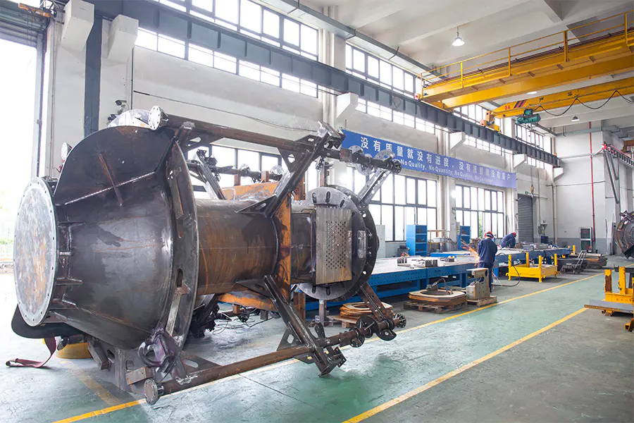
TIG, MIG, and Stick welding impose fundamentally different requirements on the desig...
READ MORE
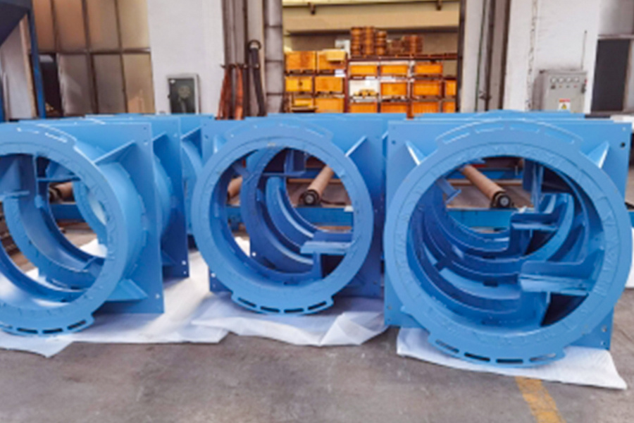
Each component in a glass production line serves a distinct and critical function. F...
READ MORE
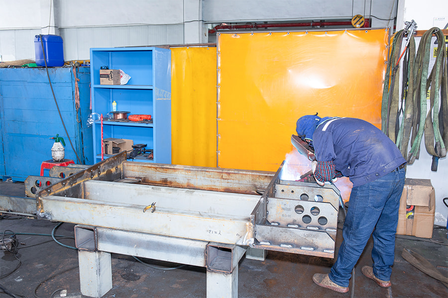
Conclusion: Welding Processing delivers superior repeatability, throughput, and lon...
READ MORE
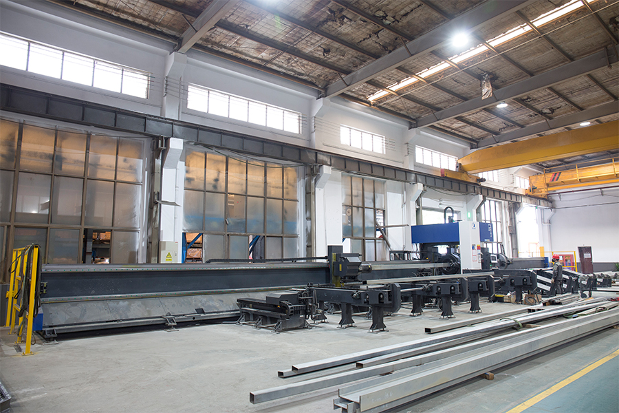
Conclusion: Proven Techniques for Superior Steel Frame Welding The most effective s...
READ MORE