English
 日本語
 Deutsch
 Español
No.158, Baoqun Road, Yaozhuang Town, Jiashan County, Jiaxing City, Zhejiang Province , China

Content
Picture a batch of fabricated brackets arriving at an assembly line on a Monday morning. Most pieces look fine from a distance, but during inspection a technician finds small pores along several seams, a few cracks near the heat-affected zone, and frames that no longer sit flat on the fixture. Rework takes a week, the delivery date slips, and the project manager starts asking which step failed. The uncomfortable answer is that most welding defects are preventable, and the warning signs were visible long before the parts left the shop.
This guide walks through the most common issues in welding processing, from porosity and cracking to distortion and undercut. For each problem, we look at the root causes, the questions a buyer or engineer should ask, and the production controls that stop the defect before it reaches the customer. The goal is practical: help you diagnose problems faster and, more importantly, choose suppliers whose routines make these problems rare.
The examples below describe typical shop-floor practice rather than any single company. The figures are drawn from commonly reported experience and should be read as illustrations of trends, not as guarantees for any specific project.
Porosity is the formation of gas pockets trapped in solidified weld metal. It may appear as scattered surface holes or as hidden voids that only show up in radiographic or ultrasonic testing. In gas-shielded processes such as MIG and flux-cored welding, it is one of the most frequently reported defects, and it usually traces back to one of three sources: inadequate shielding, contamination on the base metal, or moisture in the consumables.
Insufficient shielding gas flow, caused by a clogged nozzle, a leaking hose, wind in the work area, or a regulator set too low.
Surface contamination such as oil, rust, paint, galvanizing residue or mill scale, which releases gas when melted.
Damp filler metal or flux that has absorbed moisture from poor storage, releasing hydrogen and steam into the weld pool.
Excessive arc length or travel speed that lets atmosphere reach the pool before it solidifies.
Surface contamination is the most common cause in shops that run mixed materials. A single batch of coated plate can produce more porosity than an entire day of gas-related problems, which is why cleaning records deserve as much attention as parameter sheets.
Does the supplier record base metal cleanliness checks, such as a solvent wipe or grinding verification, on the job traveler?
Are shielding gas flow readings logged at shift start, or is gas supply treated as a constant that never needs verification?
Is filler metal stored under controlled conditions, with issue and return logs that show how long it has been exposed?
Is there a documented acceptance criterion for porosity, referenced to the applicable standard?
Experienced fabricators treat porosity as a process signal rather than a final inspection problem. Cleaning procedures are specific, such as wiping with an approved solvent followed by mechanical removal of oxide within a defined width from the joint. Gas flow is checked with a flowmeter before each shift, and nozzles are cleaned on a fixed schedule. Consumables are stored in ovens or sealed containers according to manufacturer data, and the storage log is reviewed every week.
The sequence above summarizes a practical routine. Each step is quick, and each produces evidence that can be reviewed during a supplier audit or after a defect is reported.
Cracks are the most serious welding defect because they can grow under load long after the part has left the factory. The critical step is identifying the crack type, since each type has different causes and different remedies. Two broad families matter most: cold cracking, which forms after the weld has cooled, and hot cracking, which forms while the weld metal is still solidifying.
Hydrogen-induced cold cracking often appears hours or even days after welding. It needs three conditions at once: a susceptible microstructure in the heat-affected zone, hydrogen introduced from moisture or contamination, and tensile stress as the joint cools. Hot cracking usually appears as a centerline crack in the weld bead and is linked to joint geometry, high dilution, or a bead shape that traps impurities.
| Crack type | When it forms | Typical sign | Main control |
|---|---|---|---|
| Hydrogen-induced cold cracking | After cooling, sometimes hours later | Fine crack at the toe or root | Preheat, low hydrogen consumables, controlled cooling |
| Solidification hot cracking | During weld metal solidification | Crack along the bead centerline | Joint design, bead shape, heat input control |
| Lamellar tearing | Under through-thickness stress in thick plate | Step-like crack in base metal | Material selection, joint design, buttering |
Higher carbon and alloyed steels are more sensitive to cracking because they harden in the heat-affected zone. Preheat and interpass temperature control slow the cooling rate, while postweld heat treatment can relieve stress and allow trapped hydrogen to escape. A fabricator who welds these materials routinely ties every procedure to the specific grade, thickness and joint type rather than applying a generic setup sheet.
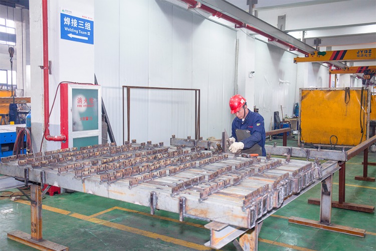
Ask for qualified welding procedure specifications rather than generic templates. A qualified procedure is supported by a procedure qualification record that documents the test coupon, mechanical test results and essential variables. When a supplier can show that a procedure matches your base metal grade, thickness and process, you have evidence that cracking risk was considered before production began. Many buyers request this documentation on a first order, and it is often the fastest way to separate a process-driven workshop from one that depends on operator judgment.
For heavier sections or custom assemblies, it can help to review the scope of welding processing capabilities before the RFQ stage, so the discussion starts from the right material and thickness ranges.
Distortion rarely causes immediate failure, but it can make a part impossible to assemble, misalign bolt holes or push a frame out of square. It results from uneven contraction as weld metal cools. The larger and more concentrated the heat input, the greater the movement, and thin sheets are especially sensitive.
Balanced welding on opposite sides of a joint, staggered short welds and back-step sequencing all spread heat more evenly. Experienced welders also control interpass temperature so the part does not accumulate heat across multiple passes. The sequence should be planned before the first arc strikes, and the planned order should appear on the drawing or in the work instruction.
Use balanced welding on both sides of a joint wherever access allows.
Break long seams into shorter segments placed across the assembly.
Select the lowest heat input setting that still meets penetration requirements.
Pre-set the assembly with a calculated offset or reverse angle where experience shows it is needed.
Rigid fixtures hold parts in position during cooling and can greatly reduce distortion. They also add cost and lead time, so the decision should be made during quoting rather than discovered during assembly. Ask suppliers to state whether a quote includes distortion control fixtures, and request a sketch or photo of the planned setup for complex frames. A supplier who raises fixture needs before the order is placed is usually demonstrating process planning rather than simply selling time.
Undercut is a groove melted into the base metal along the toe of the weld, leaving the joint with reduced cross section. Incomplete fusion means the weld metal did not fully bond with the base metal or with the previous pass. Both defects are often invisible when the bead looks neat from the outside, which makes them especially dangerous in fatigue-loaded structures.
Both defects usually reflect a parameter window that has shifted. Arc voltage that is too high can produce wide, flat beads with undercut at the edges. Travel speed that is too fast reduces fusion, while excessive current can overheat the pool and leave the edges unsupported. Operators who work from memory rather than a qualified parameter table are more likely to drift, especially on later shifts when supervision is lighter.
Visible grooves along the weld toes, especially on the upper side of horizontal joints.
Weld faces that bulge or look convex, suggesting insufficient travel speed.
Lack of wetting at the sidewalls of a groove, which points to low heat input or misalignment.
Visual inspection catches obvious undercut, but internal incomplete fusion requires volumetric methods. Ultrasonic testing and radiographic testing have different strengths, and the right choice depends on joint geometry, access and the acceptance standard. Buyers should specify the required testing level on the drawing rather than leaving it to the supplier. When the inspection scope is stated early, quotes can include the right amount of inspection time and fewer surprises appear at delivery.
The chart reflects an illustrative sample of rework tickets. Porosity and distortion lead the list, which matches the emphasis many shops place on those two issues during process reviews. The exact distribution will vary by material, process and product type.
Troubleshooting skills matter most when they are applied before problems appear. A short qualification review can reveal whether a supplier controls the variables that drive the defects discussed above, and it costs far less than a batch of rejected parts.
Procedure specificity: Are procedure documents tied to your material and thickness, with supporting qualification records?
Welder qualification: Do welder certificates cover the process, position and material you need, such as ASME Section IX or ISO 9606 equivalents?
Consumable control: Is there a documented storage and issue process for filler metal and flux?
Inspection capability: Can the supplier perform the required testing, or name a qualified partner who can?
Defect transparency: Will the supplier share rework rates and corrective action records when asked?
A strong supplier answers these questions directly and provides documents without a long delay. A weaker answer often relies on general claims of experience. Neither answer proves quality on its own, but the difference is usually visible within the first quotation cycle.
A fabrication team producing structural brackets noticed porosity during a routine audit. Of 1,200 pieces in the reviewed batch, roughly 6 percent failed the porosity acceptance check, and rework was consuming two production days each week. The design was sound and the procedure was nominally correct, so the team focused on process discipline rather than redesign.
The investigation uncovered three gaps: a gas regulator that drifted during long shifts, base plates stored outdoors before cutting, and wire spools left open overnight. The fixes were simple. Gas flow was logged at each shift start, plates were cleaned and welded within a defined time window, and spools were returned to sealed storage when not in use.
Within six weeks the porosity rate dropped below 0.5 percent. The main lesson was that the defect was not caused by one dramatic failure but by several small gaps in routine control. Buyers and engineers can apply the same approach when evaluating a supplier: look for the everyday records that prevent gaps, not only the final inspection report.
Ask the supplier what they would change after finding a defect. A supplier focused on root causes will describe the process variable involved, the record that proves the change, and how they would confirm the fix worked. Vague answers, such as improving operator skill without any process change, are a warning sign.
Not always. Many low-risk applications can rely on visual inspection and dimensional checks. Critical or fatigue-loaded structures usually need volumetric testing such as ultrasonic or radiographic methods, and the required level should be defined by the applicable code or drawing.
Include the base material grade, thickness range, joint types, inspection requirements, quantity and any drawing tolerances. Stating the acceptance standard early helps suppliers price testing and fixtures correctly and reduces revision cycles.
Simple control gaps, such as gas flow or storage practices, can often be corrected within a few weeks once identified. Problems that involve procedure changes, fixture redesign or qualification testing take longer and should be managed as a formal corrective action with defined checkpoints.
The end point of troubleshooting is not simply repairing a single batch. It is building a supply relationship in which the same defects rarely return. Porosity, cracking, distortion and undercut each have identifiable causes, and each cause leaves a trail of records that a capable supplier can show you. When you review those records before placing an order, you spend less time on rework and more time on delivery.
If you are comparing options for custom fabrication services, bring your drawings, material specifications and inspection expectations to the first conversation. A thoughtful supplier will ask about joint types, distortion risks and testing scope before quoting. That questioning is one of the clearest signals that the process has been thought through, and it is worth treating as a selection criterion in its own right.
Picture a batch of fabricated brackets arriving at an assembly line on a Monday morn...
READ MORE
When construction teams plan a rack project, one of the first decisions is where th...
READ MORE
Why Steel Structure Frame Welding Fails: A Practical Diagnosis Guide Steel structure...
READ MORE
Storage racks carry heavy loads day after day, often for decades. The welds that ho...
READ MORE
No.158, Baoqun Road, Yaozhuang Town, Jiashan County, Jiaxing City, Zhejiang Province , China
0086 13857303563
+86-573-84893330 / +86-573-84518277
product